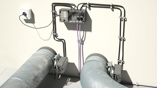
With the Wildeboer-Net BS2 communication system, Wildeboer Bauteile GmbH now offers a solution for the automatic functional test of fire dampers.
- Easy installation, commissioning and operation
- Reduction of time, costs and personnel expenditure
- Up to 3,200 metres of cable length with section-specific fault localisation
- Modules can be used and operated as independent units
With the Wildeboer-Net BS2 communication system, Wildeboer Bauteile GmbH presents a new solution for the automatic functional test of fire dampers. Building on the well-known maintenance-free nature of the Weener-based manufacturer's fire dampers, it also eliminates the need for manual functional tests on site. Thanks to its plug-and-play capability, the fully preconfigured system is easy to install, commission and operate intuitively, minimising the time, costs and personnel required. In addition, the modular communication system has cable lengths of up to 3,200 metres in conjunction with section-specific fault localisation and the continued operation of unaffected components in the event of a fault. It allows the functional test of up to 256 fire dampers. As the field modules can also be used as stand-alone components, it is possible, for example, to control two fire dampers individually without a subnet controller and bus cables.
With the Wildeboer-Net, regular checks of the functionality of maintenance-free fire dampers can be carried out completely remotely. Maintenance work on site is not necessary. The customer receives everything from the fire damper to the central operating unit from a single source. The automated test procedure also means that system availability can be monitored easily and without additional effort during the regular inspection intervals.
The communication system for fire dampers is controlled via a central operating unit, which is connected to a subnet controller via Ethernet. The latter manages up to four subordinate networks, to each of which a maximum of 32 field modules (motor or IO modules) can be connected in succession. This enables up to 256 fire dampers to be checked. The IO modules also each have eight inputs and outputs for connecting external sensors and actuators such as visual alarm indicators or fans. The maximum possible cable length between the modules is 100 metres. As all participants are designed ready to plug in for the 230 V mains voltage supply, there are no problems with voltage drops on the cables.
Each motor module monitors the operating status of up to two fire dampers with electric spring return actuators using automated, parameterisable function runs in which the fire dampers are closed and reopened. The data obtained in this way is permanently stored in the module. As the modules are independent units, most of the actions can not only be controlled remotely, but also triggered via pushbuttons on the device.
The subnet controller controls, regulates and monitors data communication in the subnets. It recognises and addresses new participants automatically, which makes commissioning the system much easier. Thanks to the peer-to-peer connections between the modules, it is also possible to localise faults and initiate residual BUS operation. Due to the galvanic isolation, the faulty sub-segment has no effect on the other sub-segments. Only the sub-segments "behind" the fault no longer take part in the bus communication. The subnet controller also communicates with the central operating unit. Here, the user can initiate function runs, sequential circuits and calendar controls via a touch display with a pre-programmed user interface, as well as view the operating and diagnostic data stored on the modules.
