
FR90 Fire damper (series FR92)
The round FR90 fire damper of the FR92 series complies with important standards and regulations. Its very large free cross-section and wide range of installation options are its hallmarks. The FR90, series FR92, is also available for installation in flexible partitions. The well thought-out design eliminates the need for maintenance to preserve functionality and makes functional tests child's play.
Technical details
- Large free cross-section for maximum volume flows and low pressure losses
- Comprehensive number of tested installation situations available
- Wall clearances (columns) of up to 600 mm possible when installed with Weichschott. [NEW] Find out more.
- MARKET PREMIERE [NEW]: Clearance up to 45 mm can be filled with fire protection foam when installed in solid wood constructions. Learn more.
- MARKET PREMIERE [NEW]: Installation in walls with clay panels enables sustainable fire protection for future-oriented construction projects. Learn more.
- Maintenance-free design: Thanks to the complete encapsulation of the operation unit, release mechanism and release element, no cleaning to maintain functionality or recurring lubrication and adjustment are necessary.
- Particularly simple functional test by opening and closing via external actuation with position indicator on site or remote actuation via building management system.
- Can be combined with the Wildeboer-Net control system
- Complies with product standard DIN EN 15650 and has CE marking
- EPD (Environmental Product Declaration)
- Hygiene certificate
Declarations & proofs
")


Product details
Wildeboer FR90 fire dampers in the FR92 series are connected to ventilation ducts in room-enclosing building elements. The FR90 fire damper has a very large free cross-section. This allows high volume flows with minimal pressure losses. It can also be used as an air transfer application in conjunction with the OR4 or OR32 smoke detector.
Design of the FR90 fire damper
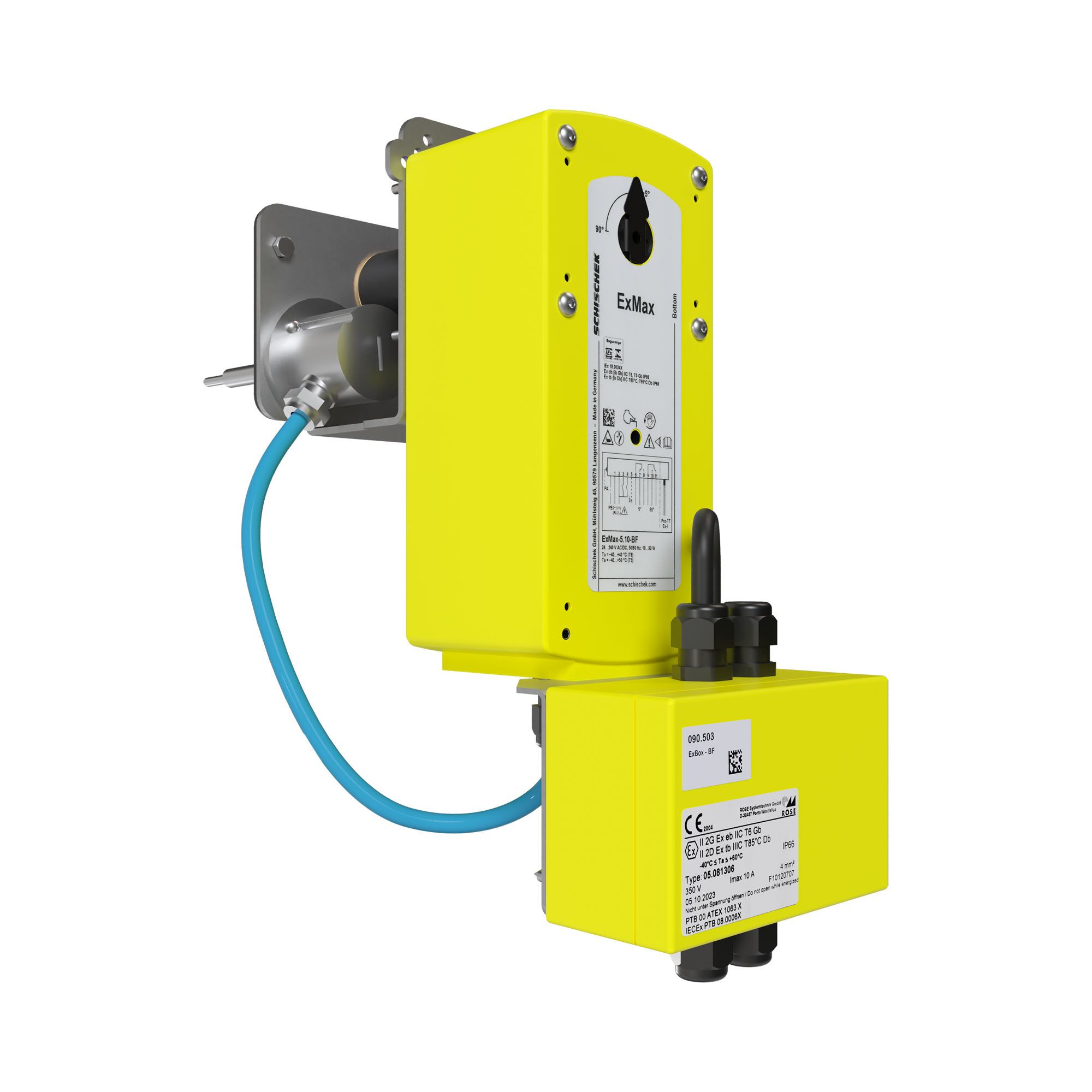
The casing of the fire damper is airtight and made of high-quality galvanized steel, combined with an abrasion-resistant calcium silicate damper blade. Optionally, this damper blade can be equipped with a metal casing made of galvanized steel or stainless steel. The encapsulated release elements activate at a nominal temperature of 70°C or 95°C. The operation units are available with manual, pneumatic or electric actuation and are also available in explosion-proof versions.
Maintenance-free design
Wildeboer fire dampers are maintenance-free by design. Thanks to their design and the materials used, FR90 fire dampers can operate without ongoing maintenance. This is achieved by completely encapsulating the drive mechanism, the thermal release device and the motor drives.
Regular lubrication is not necessary for Wildeboer FR90 fire dampers. Due to their design, there are no moving, unprotected parts inside the damper that are exposed to the air flow. In practice, this means that servicing is limited to a simple functional test of the fire dampers. This includes triggering, complete closure, and complete reopening of the fire dampers.
If necessary, repairs must be carried out in the event of damage. Cleaning for hygiene reasons must be carried out as part of the overall cleaning of the ventilation and air conditioning system or as required.
Functional tests automated
Functional tests for the fire dampers can be easily carried out and reliably documented using control software such as our Wildeboer-Net building system control.
Product markings
The maintenance-free Wildeboer FR90 fire dampers of the FR92 series comply with the European product standard EN 15650, are tested according to EN 1366-2 and CE marked.
With the present certificate MPA-BS 6000/593/18 on the fire behavior of the building materials used, they also meet the usage requirements of the Model Administrative Regulation for Technical Building Rules (MVV TB) and the Model Ventilation System Directive (M-LüAR). Wildeboer FR90 fire dampers are suitable for a fire resistance period of 30, 60, 90, and 120 minutes.
This product complies with the ATEX Directive 2014/34/EU. The fire dampers also have an Environmental Product Declaration (EPD) and a hygiene certificate from an independent hygiene institute.
New solution for use in air transfer applications
With protective grilles on both sides and in combination with an OR32 or OR4 smoke detector, the Wildeboer FR90 fire damper can also be used for air transfer applications (Ü-FR). This allows closures to be installed in fire-resistant interior walls or ceilings when openings are required for the purpose of air transfer.
Why fire dampers by Wildeboer are truly maintenance-free!
Technical specifications
Not all variant values listed here can be combined with each other. Use our Wildeboer configurator to easily check the available options.
| Nominal size |
|
| Damper blade design |
|
| Casing design |
|
| Limit switch |
|
| Release temperature |
|
| Smoke detector |
|
| Installation type |
|
| Installation variant |
|
| Drive type |
|
Product pictures


Media & Downloads
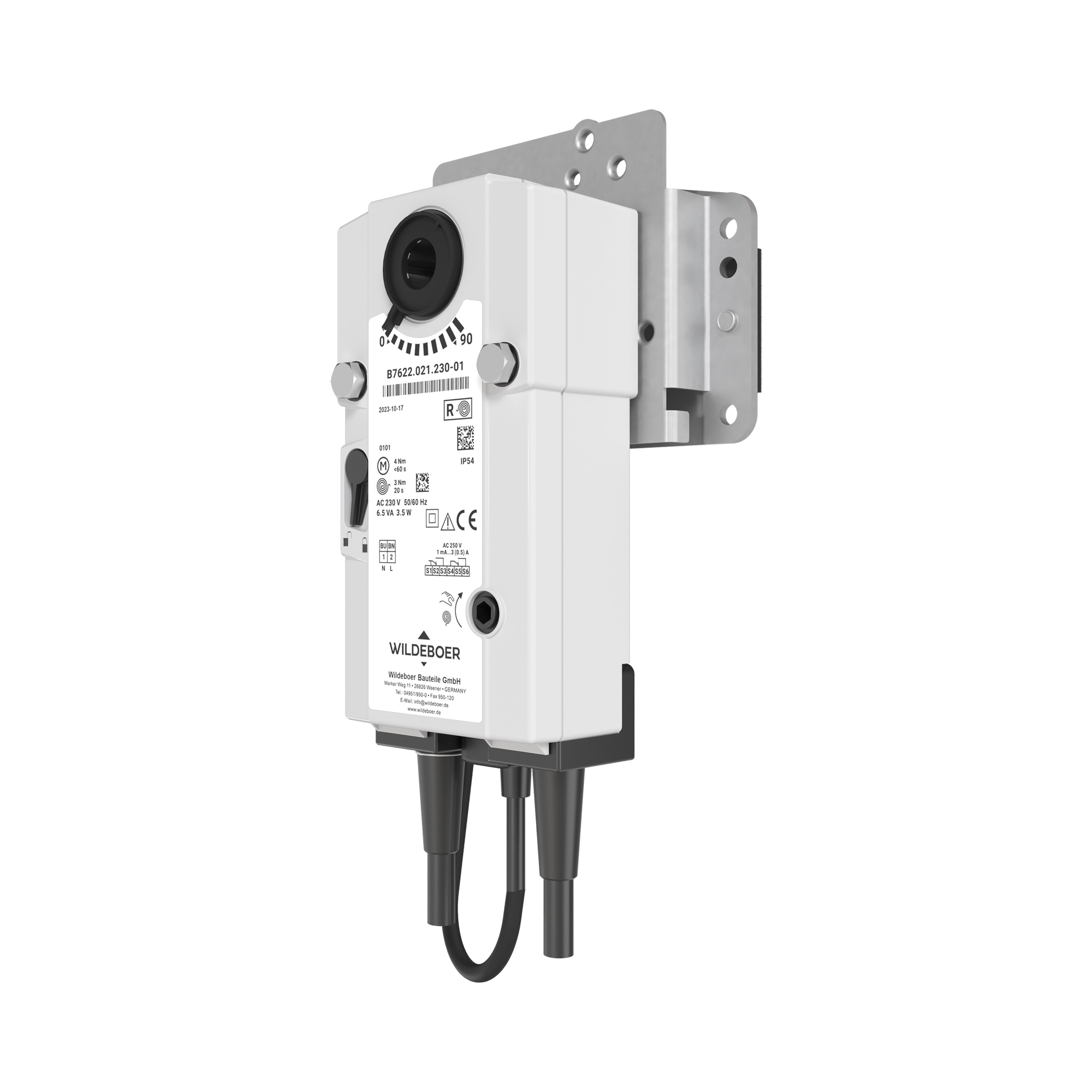
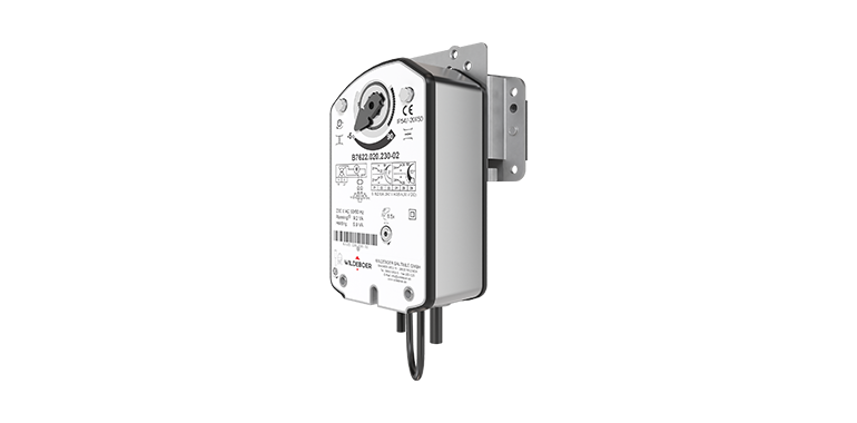
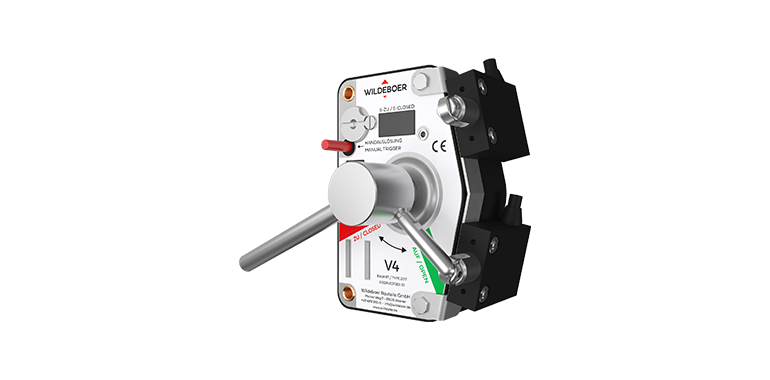
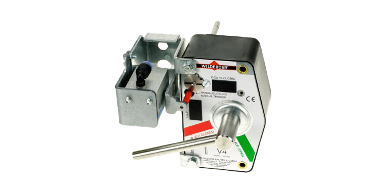
Electrical spring return actuator


- Default actuator to DN 315
- Runtime: Opening < 60 s, closing ≈ 20 s.
- CLOSED/OPEN position indicators via limit switches

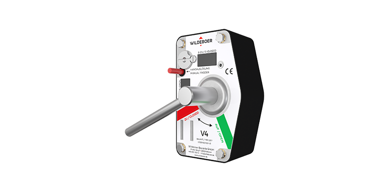
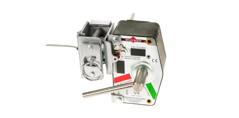
Thermal-mechanical release mechanism (TMR)

- with 70°C release element
- with coated 70°C release element
- with coated 95°C release element
- optional with limit switch


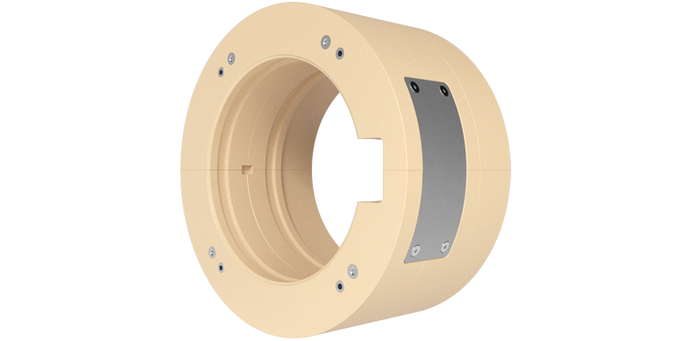
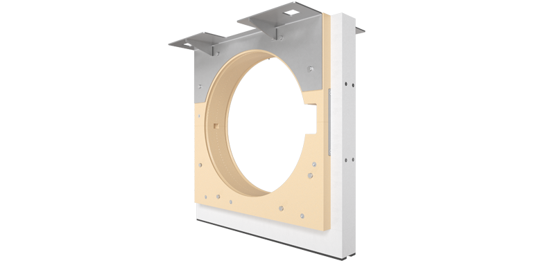
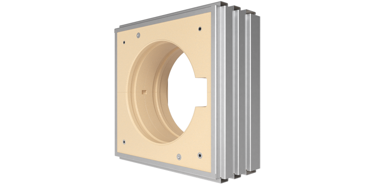
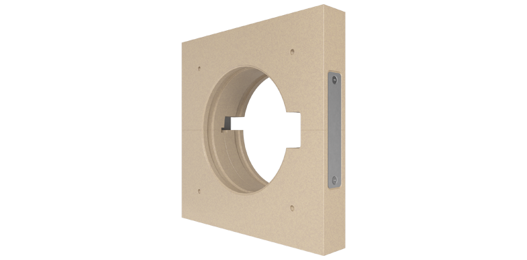
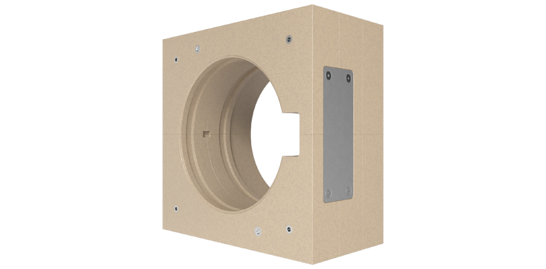
Installation and mounting subframes FR90

- For simplified installation in tapping drill holes in rigid walls and ceilings as well as in metal stud walls with cladding on both sides
- Only until DN 315

For simplified, also multiple installation in rigid walls and ceilings as well as in metal stud walls with cladding on both sides

As sliding ceiling connection when ceiling subsidence until 40 mm are to be expected and installation in metal stud walls with cladding on both sides

For bolting to rigid walls and ceilings as well as on walls with cladding on one side (shaft walls), with or without metal studs.

For connection to ventilation ducts with fire resistance period. Installation remote from rigid walls and ceilings as well from metal stud walls.

FAQ
The 92 series fire dampers are maintenance-free. Due to their design and the materials used, such as the complete encapsulation of the actuator mechanics, the thermal release device, the motorized actuators, etc., they can do without ongoing maintenance work to maintain their function. Periodic lubrication, for example, is not required. Maintenance is thus limited to functional checks (triggering and reopening of the fire dampers) or repair measures in the event of damage. Hygienic cleaning must be carried out as part of the overall cleaning of the ventilation and air-conditioning system or as required.
Due to the fact that the system is maintenance-free, functional checks may also be carried out remotely. This can be carried out particularly easily and economically via the Wildeboer BS2 communication system for fire dampers with automatic calendar control.
For this purpose, the shut-off damper blade of the fire damper must be closed and opened again. The fire damper can be equipped with different release devices or with electric spring return motors for opening and closing.
For the function test, the manual release must be operated or a remote release must be performed to close the shut-off damper blade of the fire damper. Afterwards, the shut-off damper blade must be opened again.
The respective commissioning and function control measures as well as notes on operation are described in the operating instructions.
You can find our operating instructions in the download area.
When it comes to the functioning and operation of fire dampers in accordance with DIN EN 15650, there are several specifications and obligations that must be complied with. We have summarized the essentials in a document that you can view and download here.
If the fire damper cannot be opened, the fusible link sleeve or the thermoelectric fusible link must be checked for integrity. These must be in proper condition and must not show any damage. Refer to the respective operating instructions for the design and replacement.
In addition, no installed parts may obstruct or block the damper blade freewheeling.
If these measures do not work, please contact our technical support.
You will find our operating instructions in the download area.
A minimum distance to adjacent walls and ceilings is not required when installing square fire dampers from Wildeboer Bauteile GmbH. Only a small distance is required for the round fire damper FR90.
The corresponding specifications can be found in the respective user manuals.
We have summarized details on the handling of fire dampers with asbestos-containing building materials for you in this document (german).
No. The fire dampers each have two inspection openings. These allow a view into the interior of the fire damper, on both sides of the damper blade. Inspection openings can be ordered as an option for the FK90 fire damper. These do not replace openings of corresponding size, which must be provided for cleaning purposes based on relevant standards and guidelines.
Yes, the AMP connectors can be removed.
Yes. The fire dampers are equipped with an electric spring return motor or a thermal-mechanical release device (TMA) at the factory. A fire damper equipped with a TMA at the factory can be retrofitted with a spring return motor. Complete actuator units for the particular damper type are required for the retrofit. These include the motor console, the spring return motor and the electric fusible link.
Yes, it is possible to retrofit a limit position switch for both the open and closed positions of the fire damper. Spring return motors have both limit switches as standard.
An elastic connector, also called an expansion compensator or canvas connector, is suitable for installation between a ventilation duct and components of a ventilation system, e.g. a fire damper. It can absorb changes in the length of the connected duct, burn off in the event of a fire and thus prevent the transmission of force from the ventilation duct to the fire damper.
FK90, FR90 (FR92 and FR92K series) and FK90K fire dampers are CE marked construction products according to the harmonized product standard DIN EN 15650. They can be connected on one or both sides to ventilation ducts made of non-combustible or combustible building materials. In the event of fire, thermal expansion of these ducts must not exert any significant forces on the fire damper. Compensatory measures must be provided in accordance with local requirements. In Germany, the "Guideline on Fire Protection Requirements for Ventilation Systems", or "Ventilation System Guideline - LüAR" for short, contains building code requirements for implementation and necessity. In general, compensation is achieved by suitable pipe routing. There is no general requirement for the use of flexible connectors.
In addition, when using the FK90 fire damper for commercial kitchens, the specifications of the general building inspection approval Z41.3-670 must be observed. Ventilation ducts made of galvanized or stainless steel must be connected. For the installation of the ventilation duct and limitation of forces, the above-mentioned guideline must also be referred to.
In addition, ventilation ducts on FK90 fire dampers for commercial kitchens are in accordance with the building authority approval
- in metal stud walls
- in walls made of gypsum wallboards
via suitable elastic connectors (expansion compensators) made of combustible building materials, at least building material class B2 according to DIN 4102-1. An expansion allowance of ≥ 100 mm in the installed state is required.
On 01 July 2013, the European Construction Products Regulation (CPD, No. 305/2011) came into full force in all EU member states after a transitional period and replaced the Construction Products Directive (CPD, No. 89/106/EEC).
Newly produced fire dampers that fall under the harmonized product standard EN 15650 must already be marked with the CE conformity mark since 01 September 2012. Since July 01, 2013, the manufacturer has also been required to submit a declaration of performance (DoP). He thus assumes responsibility for the conformity of the fire damper with the declared performance. The declarations of performance are available for:
As a result, Deutsches Institut für Bautechnik (DIBt) may no longer issue or extend general building inspectorate approvals (abZ) for fire dampers that fall under the harmonized product standard EN 15650 and must therefore bear a CE marking. They may no longer be required as proof of usability for national construction projects.
The information required for installation and assembly is fully described in the comprehensive user manuals.
Overflow openings ensure the flow of air between two nearby rooms, e.g. for the ventilation of interior corridors and rooms or for air supply. If overflow openings are provided in fire-resistant walls or ceilings, it must be possible to close them properly. Fire dampers with a smoke release device without connection to a ventilation duct are used here. In the event of a fire, they close the opening and thus prevent the spread of fire and smoke. With the FK90 and FR90 fire damper in combination with OR4 or the OR32 smoke release device, Wildeboer offers solutions with the necessary general type approval from the German Institute for Building Technology, which is required for use in Germany.


")

